Overall, I felt my final project of building a solar car to harness solar energy and travel the farthest distance was relatively entertaining. There are many things I felt I could've improved on while working on my project. I didn't manage my time carefully for the actual project itself, I acted as though I had all of the time in the world. I should have also tested my design more thoroughly outside on the actual pavement. For this project however, I do feel I managed my time well for the design report, I started it as soon as we were given the project and as I progressed, I'd update my report. If I had another chance I would angle the solar panel and do more research on the most efficient material to use while producing the car.
My experiences doing this project will help me with many of my future classes. We had to learn to work on our own and manage our own time. This could help with other classes when we have individual projects. I learned how to be more responsible, which is a good trait to obtain when it comes to having an actual career. While working on this project I had to present on my own in front of the entire class. I learned how to engage the students. This could help with other classes in high school and college as well, since we'll have many more presentations to look forward to.
Overall, although it was hard and I did slack off once in a while, I believe I managed my time well since in the end I completed the project on the exact due date. Writing a 10 page report wasn't too difficult, since I did it gradually, piece by piece. Writing the actual report and formatting it was rather simple in my opinion. Preparing the actual presentation was easy. However, when it came to presenting it was nerve wrecking and simply terrible. I get far too nervous when it comes to presenting in front of others because I feel like they're judging everything I say and the way I physically present myself. It was also hard for me to focus on engaging the audience when the only thing I could think of was getting over with the presentation. Nervertheless, I got through it and was proud of myself.
Working by myself differed from working in a team. I didn't have anyone to guide me when I needed help. I also had to be more responsible and focus on managing my time and completing the objective of my project to the best of my ability. It was also less stressful because I could do everything my way, I didn't have to consult anyone. It was easier to write my report since working collaboratively is one of my weaknesses. Most of the time in groups, I usually end up doing most of the work, so it was better working individually. The only person I had to rely on was myself and that's the way I like it.
Overall, I enjoyed this final project. However, I feel like I would have had more fun if I did a cosmetic project. It seemed more entertaining and easier. Nevertheless, I found this final project entertaining and a positive experience.
Link to design report
Monday, June 10, 2013
Sunday, June 2, 2013
Solar car progress report number 7!

 Our solar cars must be completed in a few days. I've been able to complete my third prototype. I've already talked about my first prototype in my previous entry, therefore I won't spend time explaining it again. My second prototype is made out of balsa wood. It consists of two 3'16 wooden inch dowels for the axles, four CD's for the wheels, four rubber stoppers for the hubs, and two straws for bearings. This prototype ended up failing because when I tested it out I found the wheels were still unable to move. They were too heavy and caused too much friction. Therefore, I decided to make my prototype using gears. I used four gears, all of the same size. I found that this worked better. For the two front wheels I decided to use two gears on each side and for the back wheels, one gear on each side. I tested it out and although it worked, it was still too heavy, since the solar panel doesn't conduct enough energy. Therefore, for the fourth prototype I decided to only use two wheels in the front and two wheels in the back. I found that the motor has to be connected carefully or else it won't allow the wheels to spin properly. I also realized putting duct tape on the connectors, causes issues with the conduction.
Link to design report- (In progress)
Saturday, May 25, 2013
Solar car progress report number 6!
I've finished my first prototype. It consisted of a chassis made out of balsa wood, four wooden wheels, two 3'16 wooden inch dowels for axles, eight rubber stoppers for hubs, and straw for the bearings. The hubs were placed on, one on both sides of each wheel to hold it in place. On the left side of each axle there was one gear placed before the wheel. The motor was attached to a gear and the solar panel was placed in the center of the chassis. The prototype ended up failing before I even had a chance to test it. The wheels were too heavy for the solar panel to power. It caused too much friction. Therefore, for prototype two, which I'm currently building, I'm using CD's for the wheels. I'm testing out CD wheels because although the pavement of the court yard is bumpy, there's a slight chance it may work. As they say, you'll never know unless you try. I've also started my design report and completed whatever I was able to do. As I make changes, I'll update my design report steadily Below is a picture of my first prototype, which was unable to be photographed because I forgot. Therefore, I depicted it by a sketch. However, the rest of my prototypes will be photographed.

Link to design report (in progress)

Link to design report (in progress)
Friday, May 17, 2013
Solar car progress report 5!
For my solar car so far I've worked on a way to test my robot. I decided I'd test it out the exact way we were able to test out our coaster cars previously while working on the coaster car project. I decided I'd line 10 meter sticks up. I'd have the car travel until it reaches the end of the 10 meter sticks. While it does this I'll use a stopwatch to see the amount of time it took for the car to complete this action. I'll place a ruler onto the ground and then measure its distance away from the straight line. I'll find the speed using distance over time. I proposed my testing idea to Mr. Carpenter and it has been approved. I'm now working on building my solar car. I've bought all of the necessary materials. I'm cutting the chassis to fit the exact measurements that I drew in my detailed drawing. I'm progressing steadily if I must say so myself. I must continue to progress gradually, in fear of falling behind.
Link to design report
Link to design report
Tuesday, May 14, 2013
Solar car progress report number 4!
Today I was able to do my elevator pitch. I completed my detailed design. The way that it works is there's one gear connected to an axle. That gear is connected to another gear which is connected to the motor. As the gears turn, the wheels will turn as well. This is how I plan on enabling the car to move. The solar panels will be placed horizontally onto the center of the car. I plan on building a car with a length of 12 cm and a width of 11 cm. The chassis will be made out of plastic cardboard, being light weight and strong. The wheels are toy car rubber wheels, since it's strong enough to travel onto the rocky pavement of the courtyard. The bearings are straws, the axles are 3'16 wooden inch dowels, and the hubs are rubber stoppers. This sums up my detailed design.


Solar car progress report number 3!
I've chosen each functional part of my design. The chassis will be made out of plastic cardboard, since this is light weight, strong, sturdy, and inexpensive. While doing research I found that light weight would be better because the car would be more stable. There will be four wheels, which will be made out of rubber, seeing as it's from a toy car. I felt that rubber would be best because it'd be able to travel easily onto the bumpy pavement of the cemented court yard, where we will be "racing" our final designs. The four axles will be 3'16 inch wooden dowels since it's inexpensive. The 4 hubs will be rubber stoppers since they fit easily onto the axle and stop the wheels from popping off. The 4 bearings will be straw because it fits into the axle well and you can basically buy them anywhere. Since I've chosen my functional parts, I will now be able to create a detailed design.
Saturday, May 4, 2013
Solar car progress report number 2!
I've researched many ideas on what the solar car should be constructed out of. I'm currently brainstorming options that would make the car as efficient as possible. For example, I know the solar car must be made out of safe material, therefore while researching I can take into consideration the safest materials. Using the criteria and constraints I was able to create a morphological chart. For the next step, through research I'll be able to choose the best material / objects for each functional part of the design. After I do this I'll be able to move onto finally constructing a detailed drawing for my solar car, which ultimately will lead up to my elevator pitch.
Morphological Chart
Wheels
|
Axles
|
Body
|
Bearing
|
Toy car wheels
|
3’16 wooden inch dowel
|
Plastic cardboard
|
Straw
|
Lego wheels
|
Pencil
|
Cardboard
|
Lego bearings
|
Can tops
|
Toy car axle
|
Styrofoam
|
Washers
|
Colored pencils
|
Lego base plates
| ||
Chopsticks
|
Balsa wood
|
Saturday, April 27, 2013
Solar car- progress report number 1!
As you can recall from my past blog posts, it's time to construct our own final project. I chose to  construct
a solar powered car, using two solar panels, a switch, and connectors.
I've finished finding the criteria, objectives, and constraints.
However; Mr. Carpenter hasn't given it back yet with the corrections so
I'm not sure if what I speculated was right.
construct
a solar powered car, using two solar panels, a switch, and connectors.
I've finished finding the criteria, objectives, and constraints.
However; Mr. Carpenter hasn't given it back yet with the corrections so
I'm not sure if what I speculated was right.
I believe the objective is to harness the energy of the sun through solar panels, enabling the car to move. Criteria are things that can be measured and they show the quality of the design. Below is a list of criteria I created for the solar powered car.
-Cost
-Energy
-Weight
-Size
Constraints are things that must be followed. Below is a list of constraints that I found for the solar powered car.
- Must be powered only on solar energy.
- Must not use dangerous material.
- Material must not be prepackaged.
- Must be inexpensive.
- Must move freely without interference / be autonomous, after flicking the switch on.
- Must be able to move after harnessing energy.
I finished defining the problem, therefore now I have to generate ideas, which is the second step out of eight in the design process. I am currently brainstorming ideas by making a morphological chart and doing research. I'm thinking of the material, wheels, hubs, axles, how the panels, switch, and connectors will connect onto the robot, and the objectives, criteria, and constraints. Thus, I'm moving on slowly through the design process, yet gradually. I should be able to keep up a steady pace if I stay highly motivated.
construct
a solar powered car, using two solar panels, a switch, and connectors.
I've finished finding the criteria, objectives, and constraints.
However; Mr. Carpenter hasn't given it back yet with the corrections so
I'm not sure if what I speculated was right. I believe the objective is to harness the energy of the sun through solar panels, enabling the car to move. Criteria are things that can be measured and they show the quality of the design. Below is a list of criteria I created for the solar powered car.
-Cost
-Energy
-Weight
-Size
Constraints are things that must be followed. Below is a list of constraints that I found for the solar powered car.
- Must be powered only on solar energy.
- Must not use dangerous material.
- Material must not be prepackaged.
- Must be inexpensive.
- Must move freely without interference / be autonomous, after flicking the switch on.
- Must be able to move after harnessing energy.
I finished defining the problem, therefore now I have to generate ideas, which is the second step out of eight in the design process. I am currently brainstorming ideas by making a morphological chart and doing research. I'm thinking of the material, wheels, hubs, axles, how the panels, switch, and connectors will connect onto the robot, and the objectives, criteria, and constraints. Thus, I'm moving on slowly through the design process, yet gradually. I should be able to keep up a steady pace if I stay highly motivated.
Monday, April 22, 2013
Constructing our Robot! (reflection overall)
 Overall I felt the entire project of building a robot, which could carry a AA battery to charge each of four electric cars parked in the
parking lot to be adequate. It was somewhat fun but also stressful, since the robot would always malfunction when it came to the code. Using scratch was quite difficult and confusing in my opinion. However, overall the entire project as a whole was okay. It wasn't the best project that we've done, however I enjoyed it. Building the robot itself and prototyping the design was simple. Programming the robot and finding its function, while graphing it and recording the data as we timed it for the amount of distance it went was more complexed. However eventually we finished right on time. Unfortunately, our robot malfunctioned while we were testing it in the actual course. It ran straight into the parking lot, knocking over cars. We received 0 points, meaning we failed to meet the objective of this design. Nevertheless, we gained experience out of this design and found enjoyment in working together. My group consisted of Mykiela, Evelyn, and Christian. They were easy to communicate with and made the entire design process enjoyable. Constructing a design report as a group was difficult since others put in more work than some and it was hard to collaborate. I find it harder to work as a group rather than alone on google docs, since collaborating writing is one of my weaknesses. Making the presentation went smoothly since we already had the design report as a base to help us make the slides. Hopefully, our presentation goes well. Overall this project was moderately pleasant.
Overall I felt the entire project of building a robot, which could carry a AA battery to charge each of four electric cars parked in the
parking lot to be adequate. It was somewhat fun but also stressful, since the robot would always malfunction when it came to the code. Using scratch was quite difficult and confusing in my opinion. However, overall the entire project as a whole was okay. It wasn't the best project that we've done, however I enjoyed it. Building the robot itself and prototyping the design was simple. Programming the robot and finding its function, while graphing it and recording the data as we timed it for the amount of distance it went was more complexed. However eventually we finished right on time. Unfortunately, our robot malfunctioned while we were testing it in the actual course. It ran straight into the parking lot, knocking over cars. We received 0 points, meaning we failed to meet the objective of this design. Nevertheless, we gained experience out of this design and found enjoyment in working together. My group consisted of Mykiela, Evelyn, and Christian. They were easy to communicate with and made the entire design process enjoyable. Constructing a design report as a group was difficult since others put in more work than some and it was hard to collaborate. I find it harder to work as a group rather than alone on google docs, since collaborating writing is one of my weaknesses. Making the presentation went smoothly since we already had the design report as a base to help us make the slides. Hopefully, our presentation goes well. Overall this project was moderately pleasant. Links
Design report- click here
Presentation- click here
Sunday, April 14, 2013
Wind turbine vs Robot design

 The wind turbine project that we completed previously differed a lot from our current project, building a robot. The wind turbine's objective had been to create electric energy efficiently while using wind power while the robots objective is to carry a AA battery to charge each of four electric cars parked in the parking lot. Both of the projects used hubs, axles, and cardboard. None of the items were allowed to be prepackaged in either project and the materials used had to be safe. I'd say the wind turbine project was a lot simpler than the robot project. The robot was more complexed, since we had to program it and create an elaborate code. Scratch was relatively difficult to use because it was somewhat confusing. The wind turbine project wasn't difficult since the only thing we had to do was create the blade shape and test it out until we finally came to an appropriate wind speed. However, for the robot design we weren't able to fully ensure our robot would function properly in the course. Although we didn't have as many prototypes for the robot design as we had for the wind turbine design, it had to be more precised and took longer. Overall, I believe the robot design had been the most intricate project that we've had so far.
Saturday, March 23, 2013
Robot Progress #2
 Mr. Carpenter changed the objective of the design. Now, instead of having the robot go around a course and roll a ball into pins, it is now carrying an AA battery to charge four electric cars parked in a parking lot. In order to charge the car the robot has to connect its battery to the car's charging contacts for at least three seconds. My group has finally finished creating a function for our robot while testing it out with different distances. We decided to go up by 0.2's and we stopped at 1.0. With the function we've been testing it out to find the distances it must go in order to stop at the car's charging contacts. We've also gotten the car to stop at the first two charging contacts and turn from there. In order to this we've set up our own course using two white boards and an expo marker to draw the charging contacts. With a few days left to obtain a substantial robot I believe we're progressing well.
Sunday, March 17, 2013
Progress: Robots Edition
 Throughout this year in engineering class, we've gone through various projects, in which we constructed many things for different purposes, fulfilling a different objective each time. At the moment, we're currently working on a robot, which will be able to travel a certain distance, roll a ball to knock over pins, and travel another specific distance to go around the pins to knock them over. We'll earn a certain amount of points for each and in the end the winner would be the individual who obtained the most points. My group is progressing relatively well. However, we're going at a moderate pace to ensure that it'll work well. We've currently built the model out of cardboard and it is able to move using four CD's as wheels. It's well stabilized and we've been able to program it using a program called "Scratch." We've programmed it to move forward and turn. If we pick up our pace I'm sure we'll be able to complete our robot within the same time that everyone else does.
Saturday, March 9, 2013
Our Journey Through our Wind Turbine!
In order to create our wind turbine we had to go through a process called the design process. This is an eight step process used by engineers in order to create a specific design to complete an objective, criteria, and constraints. The eight steps are defining the problem, generating ideas, selecting a design concept, developing a detailed design, building the prototype, evaluating the prototype, refining the design, and last but not least communicating the process and results.
The first step in the designing process is defining the problem. In order to do this we looked at the objective, criteria, and constraints of the design in order to find out the significance of the project. For example, the objective was to create electricity efficiently and elegantly using wind. Therefore, we knew we had to create a wind turbine that could use wind to create electricity. We used the criteria and constraints as a base to help us figure out what we were trying to create more thoroughly. This step helped with the overall project. This is because without this step we wouldn't have a "base" for the prototype. We'd have no idea what the design was suppose to do, therefore we'd be completely stuck on moving forth with the project. I believe I'm quite proficient at this step because I typically am able to define the problem with no issues. For instance, when Mr. Carpenter gives us a worksheet and tells us to define the problem of the design, I usually get it within a few minutes.
The next step in the designing process is generating ideas. For this step we used a morphological chart and brain stormed ideas for our wind turbine blades. For example, an idea I had was to use three curved blades made out of plastic cardboard because it's similar to a fan and it'd be light weight, which we found was best. I believe I've gotten a lot better at this step through out our projects because with a bit of brain storming and group cooperation I've been able to come up with a variety of ideas. This step is important because without it we'd have no ideas to select from in order to begin creating a prototype and carrying on with the design process. This step gives us a well organized outline of things we could choose from.
The third step is selecting a design concept. For this step we did research on what factors we should consider for turbine blades to choose the best ideas out of the designs we had. For example, through research we found out that a negative angled blade worked a lot more efficient than one angled positively, therefore we decided to angle our blades negatively. This step was important because without it we wouldn't have been able to develop a design because we needed an exact outline on our design and what we'd use to create them. I believe Tanzim and I both cooperated well and were able to master this skill.
The next step is developing a detailed design. In order to complete this step we used the ideas we selected and created an outline for our design. We included measurements to be precise so that when we were ready to prototype we'd know exactly what we were building. For example, we showed the blades were angled -15 degrees by drawing a view of the blades itself. Without this step wed' have no idea how our prototypes would look and be constructed, therefore we'd be unable to build it. This step was difficult for me because I'm terrible at making 3-D drawings and different views of a design. It's mainly because I can't imagine the design itself from different views.
The fifth step is building the prototype. To complete this step we used our detailed design that we created in the last step, to build the prototype. We drew the drawing to scale, using the measurements. This step was made a lot simpler because we had the detailed drawing. However, I had some trouble with this step because it was difficult creating the blades to be exactly as it was made on the paper. This step was important because if we didn't create a prototype we'd have nothing to evaluate or complete.
Next, we evaluated the prototypes. For this step we connected the hub of our wind turbine to a stem. We then connected the turbine to a resistor and used a twenty inch box fan as our wind source. We made sure the turbine was a meter away from the box fan. We calculate the voltage drop on the computer. Our first prototype had a voltage of .43 V. This step wasn't difficult except for finding out the rest of the data such as efficiency, which we had to do math for, which I'm not exactly superior at. This step was important because we needed to test the prototype before we decided what should be improved.
The seventh step was refining the design. In order to complete this step we used the information the class found to be true, as well as what we noticed worked better for our prototype to improve the design. For example, we noticed the less the angle of the tilt, the more power, so we decided to use a negative 10 degree angle. This step was repeated many times as we kept on creating various prototypes to find the best one. This step helped us create the most efficient design because we were able to see what was needed to be fixed and improved. We were able to fix our errors to create an efficient and final design. I believe I'm proficient at this step because we've done it quite often and I've worked well with my partner. We were able to get this done with no issues. Eventually, after refining the design multiple times, we came to a final design of two rectangular shaped blades made out of plastic cardboard. It was tilted negative 10 degrees, and had a length of 15 cm and a width of 6 cm.
Last but not least, step eight is communicating the process and results. To do this we recorded our data and findings and created a design report and presentation, which could be seen below. This step wasn't as difficult as it seems because I had a partner who I worked well with. We were able to get this done with time and planning. We didn't have any issues with finishing the work in the time limit and since we cooperated well it was simple. At last, we complete the eight steps of the design process.


Friday, March 1, 2013
Final Design Ideas!
As you know the end of the end of the year is rapidly approaching. Soon it'll be time to create our own final designs based on an idea/ invention we find intriguing and are able to construct. It won't be easy, but with time, patience, brain storming, and research we'll be able to successfully complete a design of our own. The hardest part of this final design is actually creating the invention or idea itself. It can't be too complex and it should be fulfillable, considering the time limit, price range, and the fact that it has to be functional and efficient. Below are a few ideas I have for a design of my own.
1.) A computer program which teaches simple math to children. For example, 1+1, 2+7, 9+1, etc. It'd be useful because they'll be able to easily access this program which will help them progressively advance slowly yet surely in math. Sure, it may be simple math but every child needs to learn the basics before they move onto more difficult problems.
2.) Every child has that phase where they carry lunch bags to school. However, doesn't it frustrate them when they're sitting at lunch and they realize that their food has already grown cold? Well it sure would frustrate me. Therefore, I believe making a lunch box or a similar compartment that kept food fresh and warm would be an essential design. This design would ensure that their food would keep fresh and delicious. In fact, regardless of your age, whether you're a child or not, it wouldn't matter, we all could use this "lunch box."
3.) Another idea I have is an alarm that alerts you when someone enters your room, a bag of yours, or even a personal belonging that you don't want anyone snooping through. There could be some sort of device that allows the alarm to sense when someone opens it and when they proceed to open it, it'll enable the alarm to go off. This is perfect for ensuring your belongings safety.
As you can see, these are a few of the ideas I've come up with for my final design. I still have a ton of brain storming to do, in fact I'm not positive if I'll even use any of these ideas. However, with research I'll eventually find an idea that I find approachable and appropriate for this project.
Saturday, February 16, 2013
Group Presentations!
 Last time my groups presentation went well. We all did an equal amount of work and were able to cooperate well while using google docs to create it. Personally I had no problems with my group members. However, I could have done a better job at making eye contact with the audience while presenting. I didn't engage the audience members, I was rather blatant and straightforward. I believe I could have done a better job at making the presentation enjoyable. I projected my voice fairly well during the last presentation because every one in the room had been able to hear me. This time for our presentation I will try not to read off of the board too much and I'll try to engage the audience. Making the presentation itself wasn't difficult because my group member and I both put in a fair amount of work and effort while creating it. We gave each other advice on what we needed to work on and improved our writing skills. Each of the slides we created are very brief including bullet points and are comprehensible, seeing as the slides aren't too "flashy." Overall, I plan on improving my presentation skills with help from what I've learned from our last group presentation.
 Friday, February 8, 2013
Wind Turbine Report- Collaborating With My Group!

 As you may have read in my recent entries, in engineering class we're currently creating wind turbines. My partner, Tanzim and I have finally completed our design. We've progressed far in the past few weeks, seeing as we're now working on the "designing process" section of our design report. The design report is basically a step by step report on how we created our wind turbine blades, the prototypes, and the conclusions we've made about developing them. Tanzim and I have met on google docs every day and we've been splitting up an equal amount of work for each of the sections. We've been working vigorously and persistently because we felt it'd be best if we took our patience and time while developing this design report so it'd be useful and accurate. We help each other enhance our writing and correct mistakes we've made. My partner's easy to work with and collaborating with him isn't an issue at all, especially since we've worked together before. Overall, using google docs and cooperating with one another hasn't been a problem.
Saturday, February 2, 2013
Wind Turbine Blades (Update)
On friday in Engineering Class, Mr. Carpenter had told us to grab white boards and start making 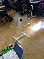 notes of things that we've noticed works best for our wind turbine blades throughout our several prototypes. My group had done two different prototypes. One with a blade angled 15 degrees and another with the blade angled negative 15 degrees. By doing so we realized that a blade angled negative 15 degrees works a lot better than a blade angled positive 15 degrees. The difference was small yet significant, a blade angled 15 degrees went .34 mW and a blade angled negative 15 degrees went .37 mW. Therefore, as you can see we came to the conclusion that a blade angled negative 15 degrees works better than one angled positive 15 degrees. Note, negative means it spins counterclockwise and positive means it spins clockwise. Thus, if you plan on creating a wind turbine, it will be more efficient if you make the blades spin counterclockwise as opposed to clockwise. So far, this has been our progression on what we've noticed throughout our many prototypes for this assignment.
 notes of things that we've noticed works best for our wind turbine blades throughout our several prototypes. My group had done two different prototypes. One with a blade angled 15 degrees and another with the blade angled negative 15 degrees. By doing so we realized that a blade angled negative 15 degrees works a lot better than a blade angled positive 15 degrees. The difference was small yet significant, a blade angled 15 degrees went .34 mW and a blade angled negative 15 degrees went .37 mW. Therefore, as you can see we came to the conclusion that a blade angled negative 15 degrees works better than one angled positive 15 degrees. Note, negative means it spins counterclockwise and positive means it spins clockwise. Thus, if you plan on creating a wind turbine, it will be more efficient if you make the blades spin counterclockwise as opposed to clockwise. So far, this has been our progression on what we've noticed throughout our many prototypes for this assignment.
Monday, January 21, 2013
Wind Turbine Blades- Our Progression
As you may have read about in my recent blog, we are currently working on wind turbine blades in engineering class. My groups consists of two guys named Tanzim and Alex. We decided to create our wind turbine blades out of plastic cardboard because it's lightweight and sufficient. We decided to start off with a simple design of a width of 8 cm and a length of 20 cm. We created a rectangular blade and are currently still testing because we created various prototypes for out first prototype because we only had minor changes. (We had a prototype 1a and 1b.) It had taken us a while to complete our first prototype because it took us a while to consider each of our ideas. We've completed our first prototype and are moving on to testing. We haven't gotten too far ahead of what we initially thought we would have done by now. However, we're steadily moving further into the designing process. We're taking our time and being careful because one mistake could completely throw off our entire design. Below you will see pictures of one of our recent prototype, prototype b.


Saturday, January 12, 2013
Wind Turbine Blade Design!
 Temperatures are increasing rapidly, in fact we've barely had a snow day this year. Global warming is worsening and flooding and tropical storms are becoming more likely here in the U.S. Wind turbines are one of the options we've resorted to in order to help the environment. Wind turbines use wind energy to create electricity in an efficient, environmental way. In engineering class for this unit we're working on creating the most competent wind turbine blade. I believe my design of two blades made out of plastic cardboard will meet the objectives of this design, which is to produce electricity using wind in the most elegant and efficient way. I decided to use a bulged blade with a rounded top because when I thought of a wind turbine blade, I thought of a fan and the fact that they're somewhat similar and a fans blade is bulged with a rounded top. For the material I decided to use plastic cardboard, seeing as it is durable and lightweight, which will spin faster because it won't need as much wind speed to function as a heavier blade. I decided to use two blades because I believe having more blades would just create drag. I decided to use a horizontal orientation because it has a multidirectional capability and functions regardless of wind direction. Overall, I believe these decisions for my blade design will create the best functional wind turbine.
Subscribe to:
Posts (Atom)